
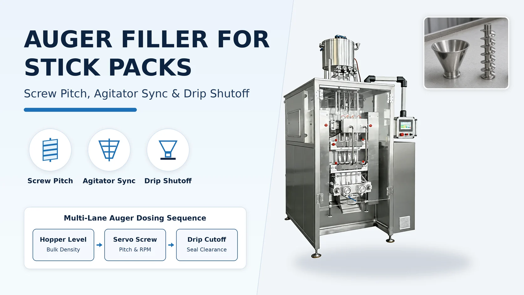
Multi-Lane Powder Stick Pack Reference Configuration and Dosing Scope
Selecting the right dosing head for a vertical stick-pack line starts with how the dry product moves from the supply hopper into each narrow forming tube. The four-lane powder reference configuration uses an independent servo auger for each lane. A four-lane powder stick pack machine reference range runs about 30–40 cycles per lane per minute, roughly 120–160 sticks per minute, using an independent auger for each lane. The powder stick pack reference fill weight is about 1–20 g per stick, while doses around 30 g require different auger tooling and a trial.
Stick envelope geometry, machine utilities, and laminate selection must be reviewed alongside the dosing head before freezing the equipment specification. The powder stick pack reference configuration forms sticks with a length of about 50–180 mm and a width of about 15–30 mm set by the forming tube. The powder stick pack reference configuration uses about 3.5–4.5 kW at 220 V or 380 V and 50/60 Hz, 0.6–0.8 MPa compressed air, weighs about 650 kg, and uses an SUS304 frame with 304/316L product-contact parts. The powder stick pack reference configuration supports heat-sealable laminates (PET/PE, PET/AL/PE, NY/AL/PE, paper/PE), back seal with straight, zig-zag, or round-corner cuts and optional tear notch, plus dust extraction and nitrogen flushing options.
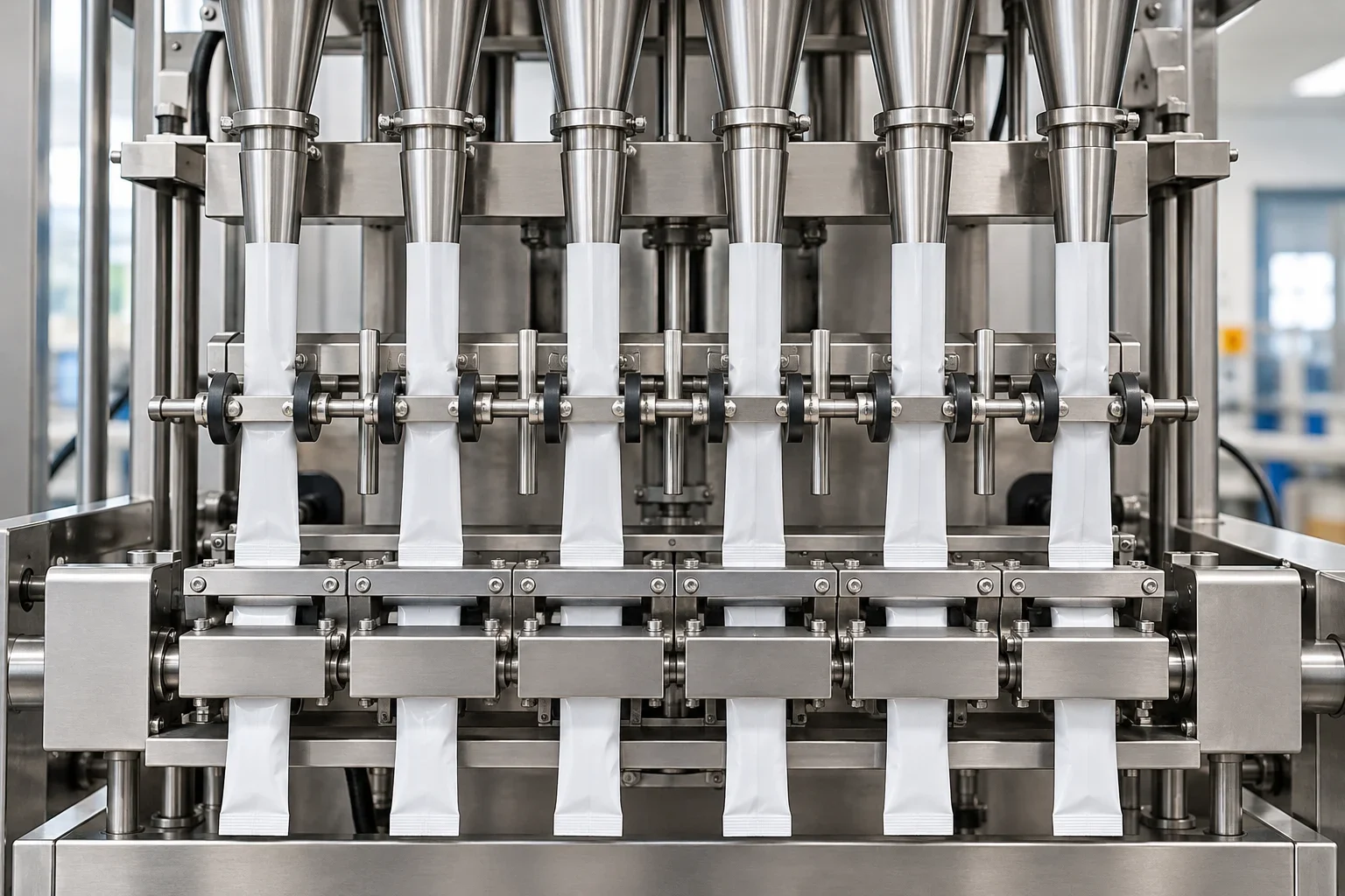
Web width planning, lane variance tracking, and alternative dosing mechanisms complete the baseline comparison across stick-pack formats. For a back-seal stick pack, unfolded film strip width is approximately twice the finished width plus the film consumed by the back seal, and reel width is unfolded strip width per lane multiplied by lane count plus edge allowance. For equal sample counts per lane using population variances with the observation count as divisor, total variance equals average within-lane variance plus the variance of lane means. Across our stick pack machine lineup, liquid and gel models use a piston or servo pump with a suck-back anti-drip nozzle (about 1–30 ml sticks or four-side-seal sachets up to about 50 ml), while granule models use volumetric cups or vibratory feeding. On our multi-lane stick pack machines, each lane has its own forming tube, so a width change requires a matched forming set for every active lane, quoted per project specification. Documenting the powder behavior, target stick width, and lane count early keeps tooling selection aligned with the packaging film and forming set.
Related reading: Powder Stick Pack Machine: Auger Dosing; Granule Stick Pack Machine: Drink Mixes
Powder Flowability, Compressibility Index, and Hopper Mass-Flow Geometry
Once volumetric auger dosing is selected, the next engineering step is characterizing how the powder piles, compresses, and discharges from the hopper. In Table 1 (Flow Properties and Corresponding Angles of Repose), an Angle of Repose of 25–30 degrees corresponds to Excellent flow, 31–35 degrees to Good flow, and 36–40 degrees to Fair flow (aid not needed). In Angle of Repose flow classification, 41–45 degrees is Passable (may hang up), 46–55 degrees is Poor (must agitate, vibrate), 56–65 degrees is Very poor, and >66 degrees is Very, very poor. The Compressibility Index and Hausner Ratio are determined from unsettled apparent volume VO and final tapped volume Vf as Compressibility Index = 100 x [(VO - Vf)/VO] and Hausner Ratio = (VO/Vf).
In Table 2 Scale of Flowability, a Compressibility Index (%) of ≤10 (Hausner Ratio 1.00–1.11) is Excellent, 11–15 (1.12–1.18) is Good, 16–20 (1.19–1.25) is Fair, and 21–25 (1.26–1.34) is Passable.
In the Scale of Flowability, a Compressibility Index (%) of 26–31 (Hausner Ratio 1.35–1.45) is Poor, 32–37 (1.46–1.59) is Very poor, and >38 (>1.60) is Very, very poor. Flow rate through an orifice is not useful for cohesive materials; general guidelines specify an opening diameter > 6 times the particle diameter and cylinder diameter > 2 times the opening diameter.
Hopper wall steepness, shear testing, and vibration sensitivity determine whether cohesive blends feed smoothly into the auger intake or stagnate above the flights. Common hopper flow problems include arching or bridging, ratholing (which can limit live capacity to as low as 10–20% of rated storage capacity), flooding or flushing, flowrate limitation, and particle segregation. A 60-deg. (from horizontal) conical hopper angle is usually not sufficient to provide mass flow for most bulk solids; wall friction and cohesive strength are measured using a direct shear tester according to ASTM D-6128. A bulk material is considered coarse if the majority of its particles are larger than 1/8 in. or 3 mm, whereas wedge-shaped hoppers can typically be 10 deg. to 12 deg. less steep than conical hoppers and still promote mass flow. Vibrators or impact hammers may collapse a hopper bridge briefly, but for pressure-sensitive materials vibration can actually lead to stronger bridges forming within the hopper. Segregation results when particles separate due to differences in size, shape, or density, and common segregation mechanisms include sifting, fluidization, and dusting. Supplying representative product batches for benchtop flow evaluation allows the tooling engineer to anticipate bridging, ratholing, or particle separation before cutting metal.
Related reading: Protein Powder Stick Pack Machine; Nutraceutical Stick Pack Machine
Scroll horizontally to see all columns. Keyboard: focus the table and use the arrow keys.
| Powder Flow Regime | Hopper & Agitator Focus | Trial Verification Record |
|---|---|---|
| Free-flowing granules and sandy powders | Pair straight auger tooling with a collector funnel and spinner plate | Check for post-stop dribble at the nozzle and record fill mass stability across steady running |
| Transitional beverage and seasoning blends | Maintain steady hopper head height through level-controlled infeed and counter-rotating blade conditioning | Compare packet mass before and after hopper refill events to verify bulk-density stability |
| Cohesive dairy, protein, and botanical powders | Break arches and ratholes above the screw intake using counter-rotating slow agitation and self-feeding over-flights | Inspect hopper walls for hang-up and log lane-to-lane dose consistency across extended runs |
| Light, fluffy, or easily aerated fine powders | De-aerate the powder column and maintain backpressure at the lower funnel lip before discharge | Examine finished cross-seals for trapped dust and verify clean cutoff after each screw stop |
Auger Screw Pitch, Inlet Loading, and Agitator Synchronization
Screw pitch geometry and flood-loaded inlet behavior govern how much powder each revolution displaces and how evenly material draws from the hopper. In KWS screw pitch capacity factors, Standard Pitch (Pitch = Diameter) has a Capacity Factor of 1.00 and Short Pitch (Pitch = 2/3 Diameter) has a Capacity Factor of 1.50. In KWS screw pitch capacity factors, Half Pitch (Pitch = 1/2 Diameter) carries 1/2 the capacity of a full pitch screw (Capacity Factor 2.00), while Long Pitch (Pitch = 1-1/2 Diameters) has a Capacity Factor of 0.67. The inlet of a screw feeder is flood loaded (100-percent); uniform outside diameter and constant pitch screws fill from the rear of the inlet first, creating rat-holing, stagnant material, and possible bridging.
To prevent rear-inlet ratholing and flooding past the screw intake, engineers match pitch progression and shroud length to the powder's transport profile. Three types of screw feeders promote even inlet draw: Variable or Stepped Pitch (shorter to longer pitch toward discharge), Tapered Outside Diameter, and Mass Flow (developed by Jenike & Johanson with variable pitch and tapered inside diameter). Screw feeders must be equipped with a shroud for at least 2 pitches beyond the inlet opening to prevent flooding past the inlet, and start-up horsepower and torque can easily be 2.5 times normal operating conditions. In a screw feeder capacity profile there are 3 characteristic pitch points: 1) minimum pitch below which product jams between the blades and rotates with the screw, 2) pitch where optimum transport occurs, and 3) maximum pitch.
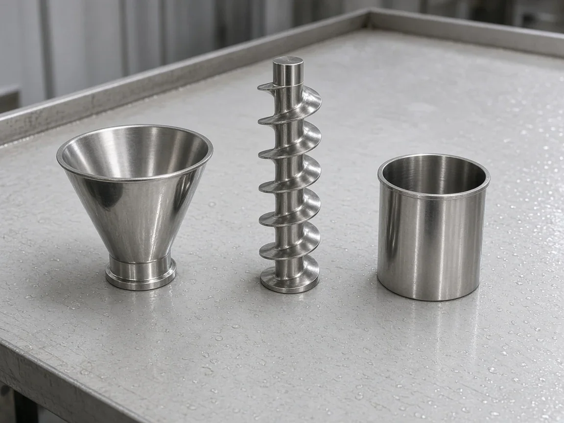
Matching the auger profile, contact-part metallurgy, and agitator blade style to the product prevents stagnation inside the hopper cone. Straight augers are typically used for free-flowing powders and are commonly paired with a slow-speed or flake-blade agitator, a straight funnel, a collector funnel, and a spinner plate. Self-feeding augers are used for non-free-flowing powders and are commonly used with a slow-speed agitator, high-speed 'D' agitator blade, and lip funnel; the top over-flight grabs and compacts product evenly while lip funnels provide backpressure so product does not drip. Our auger filler screws, funnels, and dosing tubes are machined in 304 or 316L stainless steel for all product-contact surfaces, matching our SUS304 machine frame and sanitary contact specification. A slow-speed agitator blade rotates in the opposite direction as the auger so no product in the hopper is stagnant, whereas flake blades rotate within the hopper inner dimensions so light-density flaky products do not turn together as a mass. Specifying the screw profile, surface metallurgy, and counter-rotating agitator geometry together keeps flight loading uniform across every dosing cycle.
Related reading: How a Stick Pack Machine Works; How to Choose a Stick Pack Machine
Discuss this configuration
Discuss on WhatsAppDrip Washers, Grid Restrictors, Spinner Plates, and Positive Cutoff Gates
Stopping the auger drive at the end of a dosing cycle does not automatically halt powder movement at the funnel exit. The drip washer has a beveled edge and attaches to the end of a self-feeding auger at the stem via a left-handed screw and left-handed thread tap, providing back pressure with the funnel inner lip to keep product compressed and less prone to drip. The grid restrictor is dropped from the top of the lip funnel and rests on the inside diameter of the lip to hold back product while creating additional back pressure, and when made with string or wire it is called a monofilament nozzle.
Free-flowing granules and intermediate blends require centrifugal or positive mechanical shutoff hardware to stop trickling while the vertical web indexes. The spinner plate attaches to the free-flowing auger via a left-hand threaded bolt and left-hand nut(s) and throws product outward by centrifugal force; without the spinner plate, free-flowing products pass through the auger and funnel. A collector funnel necks down the product stream from a spinner plate; collector funnel covers should be vented for air displacement, and dust shrouds use two separate tubes — one for dispensing product and the other for a dust port to capture airborne product. For 'tweener' products on VFFS applications, the pneumatic flapper gate cut-off ('duck bill cut-off') uses two pneumatically controlled gates to prevent product drip from contaminating vertical bagger seals, while cone cut-offs attach to the last flight stem.
During factory acceptance trials, inspect the lower nozzle tip immediately after screw deceleration and examine consecutive cross-seals to confirm that no tailing particles fall into the jaw path while the film advances.
Related reading: Fin Seal vs Lap Seal on Stick Packs: Film Width, Seal Layers & Dust Tolerance; Stick Pack Machine Problems and Solutions: Multi-Lane Troubleshooting, Seal Leaks & Dose Drift
Auger-to-Funnel Gap Gauging, Agitator Delay, Vacuum Closing, and Seal Integrity
Setting the radial clearance between the auger flights and the funnel wall is essential to avoid metallic galling or particle crushing while keeping post-cycle dribble under control. With non-free-flow tooling, an improper auger-to-funnel gap causes contact damage if too small or excess dripping between cycles if too large, so our assembly technicians set the tooling gap with a precision feeler gauge during head assembly and verify it during the factory trial. In particulate clearance sizing, coarse granules (~1/8 inch / 3 mm diameter) require 2–3 nominal sizes of radial clearance so crystals do not shear between the flight tip and tube wall, whereas fine powders use a close-clearance fit (0–1 size).
Drive speed control, agitator timing, and high-speed shaft blades address severely cohesive powders that stagnate in the lower funnel taper. While older clutch-brake auger heads relied on fixed three-step pulley speeds (450, 600, and 750 RPM), our multi-lane stick pack machines use an independent servo auger drive on each lane for continuous speed and acceleration-ramp control, paired with timed agitator delay so the powder bed is not over-compacted between cycles. Unlike slow-speed hopper sweeps, high-speed shaft-mounted agitator blades rotate at auger RPM to clear very cohesive products that tend to bridge in the lower funnel taper.
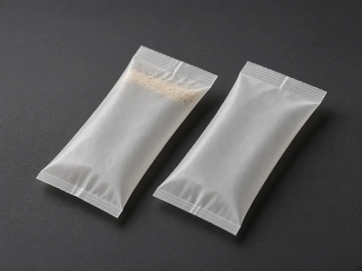
Benchtop cavity-collapse checks, positive nozzle closure, and heat-seal resin selection protect finished stick-pack seams from powder microchannels. In a narrow-dowel bench test, if the cavity created in a container of powder collapses on itself the powder is free-flowing, if the impression remains it is non-free-flowing, and partial collapse indicates a transitional powder where a beveled drip washer or grid restrictor is required. A vacuum-assisted or lip-compressed nozzle closure arrests powder trickle at the end of the dosing stroke without moving gate parts in the product stream, allowing shorter bag drop distances and cleaner cross-seal bands. In flexible packaging heat sealing, solid particle contamination may cause microchannel formation and poor integrity throughout the sealing area; low melt viscosities help encircle particles, and static charge or polarity can attract small solid particles to the sealing area. Combining proper nozzle shutoff, dust extraction, and per-lane weight verification ensures clean cross-seals and repeatable stick weights across every active lane.
Related reading: Single vs Multi-Lane Stick Pack Machines; Stick Pack Production Capacity: Lanes, Cycles per Minute (CPM), Film Splicing & Real OEE Output
Sources
- StickPackMachine — Powder Stick Pack Machine, How It Works, Troubleshooting, and Spare Parts
- United States Pharmacopeia — Powder Flow (USP <1174>)
- Chemical Engineering Progress (AIChE) — Prevent Flow Problems in Hoppers, Silos and Bins
- Jenike & Johanson — Hopper Bridging and Powder Segregation
- KWS Manufacturing — Screw Conveyor Engineering Guide
- Bulk Solids Innovation — Screw Feeder Capacity Profile
- University of Twente — Seal Integrity in Flexible Packaging