
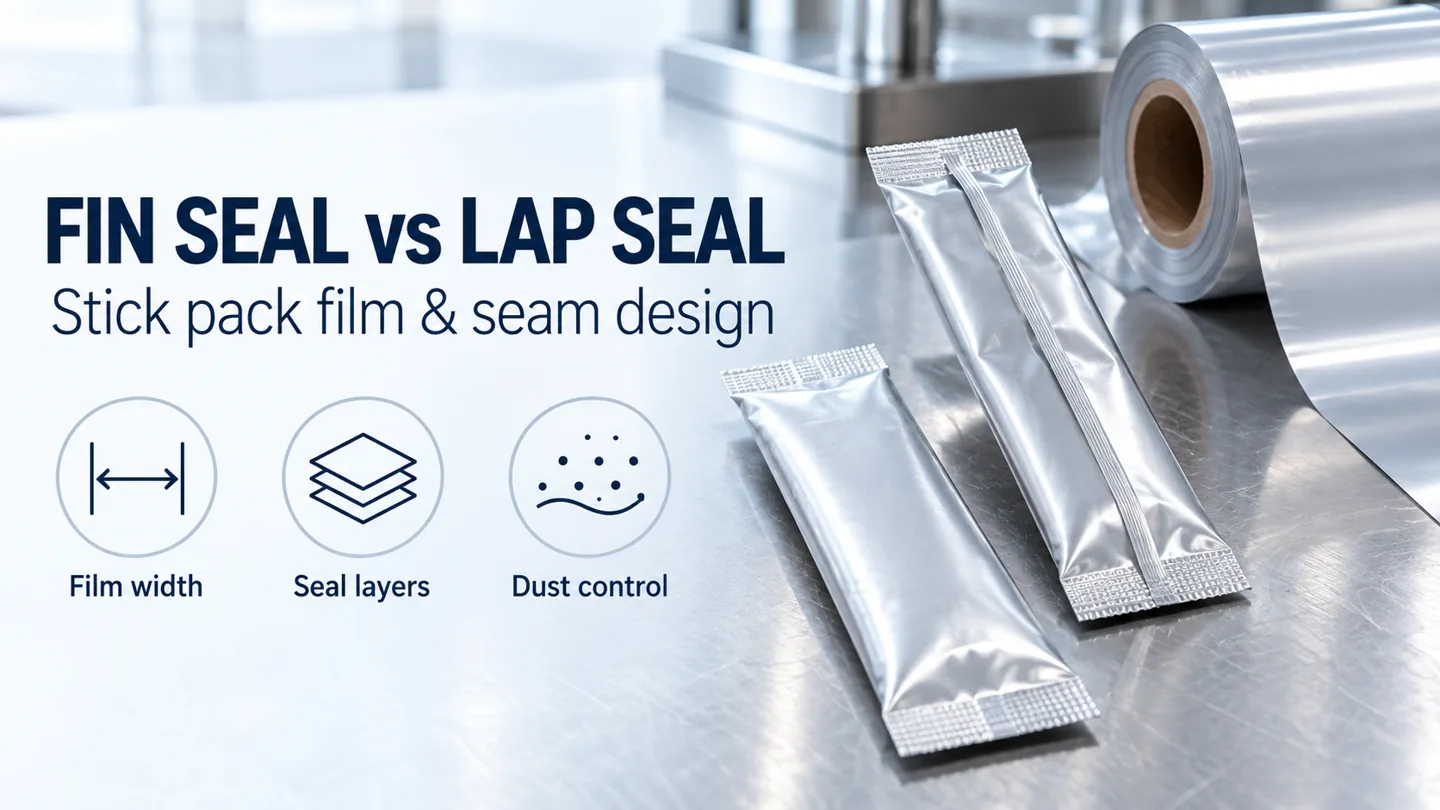
What is the difference between a fin seal and a lap seal?
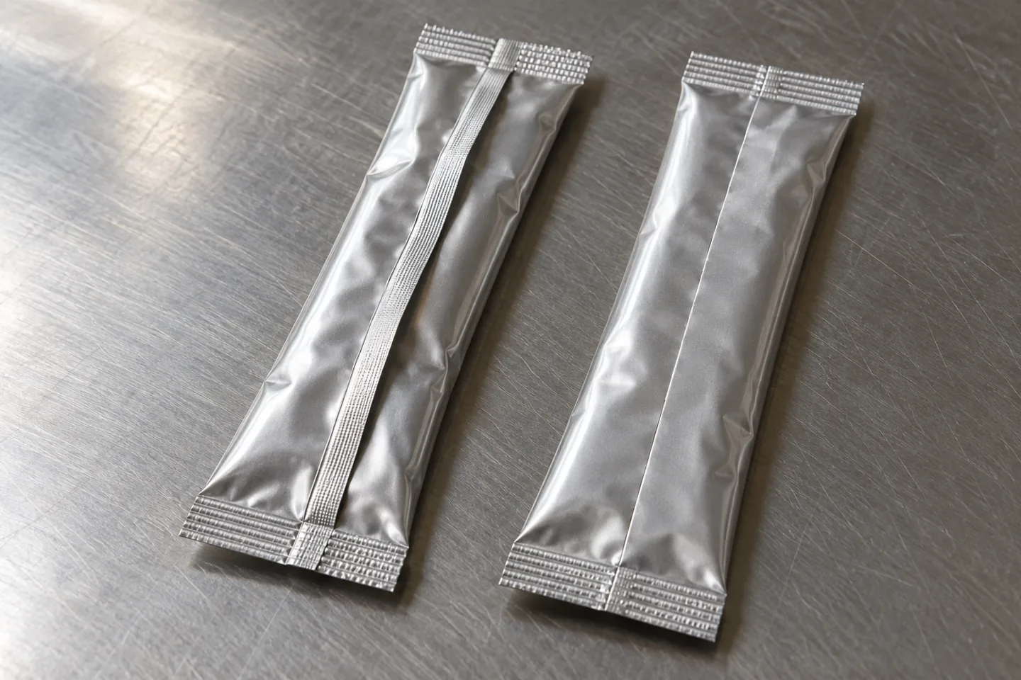
A fin seal brings the inner surfaces of both film edges together to make a projecting seam, which can then be folded against the back of the stick pack. A lap seal overlaps the two edges so that the inner surface of one edge contacts the outer surface of the other. Overlap seal is another name for lap seal. Both constructions can form the longitudinal back seal, so a request for a “back seal” should also identify which geometry is required.
Call the product-facing surface A and the outside surface B. The contact is A/A for fin sealing and A/B for lap sealing. These letters identify faces, not polymer grades: two different-looking surfaces may have compatible heat-sealable coatings, while two similar-looking films may have different sealing behavior. Keep the face labels on the material drawing and unwind sketch so the converter and equipment team discuss the same interface.
Use the table to separate the material decision from the appearance decision. A folded fin leaves a physical footprint over the rear panel. A lap seam leaves an overlap edge and conceals part of the underlying surface. Either arrangement must also meet the transverse end seals cleanly. Inspection therefore needs to follow the seam along its length and into both end-seal junctions.
Related reading: Stick Pack Machine Buying Guides
Scroll horizontally to see all columns. Keyboard: focus the table and use the arrow keys.
| Comparison | Fin seal | Lap / overlap seal |
|---|---|---|
| Film surface requirement | Inner sealant bonds to itself | Inner face bonds to the opposing outer face |
| Material around the body | Two edge allowances beyond the body circumference | One overlap allowance beyond the body circumference |
| Artwork consequence | Folded fin covers part of the rear panel | Overlap conceals part of one edge |
| Failure to prevent | Powder, wrinkles or poor bonding within the joined inner faces | Incompatible outer coating, print interference or loss of overlap |
| Release evidence | Accepted bond and finished-pack checks | Accepted bond and finished-pack checks |
Which film layers must be heat sealable?
For a conventional laminate whose inner PE layer is heat sealable and whose outer PET surface has no compatible sealing coating, fin sealing pairs the available sealant surfaces. To use a lap seal, specify an outer surface that can bond to the inner sealant at the proposed operating conditions. The laminate shorthand alone does not settle this question: coatings, surface printing and the exact resin grades can change what happens at the overlap.
Jindal Films’ Bicor 150 ASB-X data sheet provides a concrete material example: it describes a two-side-coated, sealable OPP film and identifies self-lap-sealability. The useful procurement detail is the specified surface construction. Request the exact film code and the supplier’s mating-surface information for your proposed laminate, including which face is on the inside after forming.
Check the final printed and coated construction, not just an unprinted base-film sample. Ink or lacquer on the outer face can occupy the lap contact region. Show that region on the artwork and obtain compatibility information for the actual combination of film, ink and coating. For either seal, carry the agreed temperature, dwell and pressure conditions into the trial plan; simply calling both faces “sealable” leaves the operating window undefined.
Related reading: Stick Pack Film & Machine Compatibility
How do you calculate back-seal stick pack film width?
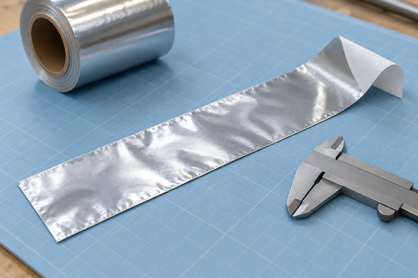
Calculate a single slit strip from the developed pack-body circumference plus the material assigned to the longitudinal seam. Define B as strip width and C as developed body circumference, excluding the seam. Define s1 and s2 as the two total fin-edge allowances, and o as the total lap overlap. Keep every dimension in the same unit and show its start and end points on the approved drawing.
The general equations are B_fin = C + s1 + s2 and B_lap = C + o. For symmetric fin allowances, s1 = s2 = s, so B_fin = C + 2s. With the ungusseted body lay-flat convention W = C/2, the formulas become B_fin = 2W + 2s and B_lap = 2W + o. W excludes the projecting fin and is not the apparent width measured across a filled, rounded stick.
An edge allowance is the full material allocation from the body boundary to the slit edge. The effective bonded band can occupy only part of it. Keep any unbonded edge margin inside the stated allowance and label the bonded width separately. Substituting a jaw-contact width for s without checking those boundaries can make the ordered strip too narrow. Where the pack geometry differs from the lay-flat convention, use C from the forming drawing.
Related reading: Stick Pack Sizes & Dimensions Guide
Scroll horizontally to see all columns. Keyboard: focus the table and use the arrow keys.
| Variable | Definition | Drawing check |
|---|---|---|
| B | One slit strip width | Slit edge to slit edge |
| C; W | Body circumference; ungusseted body lay-flat width | C = 2W only for the stated convention |
| s1, s2; s | Total fin-edge allowances; symmetric allowance | Include specified edge margins once |
| o | Total lap overlap | Distinguish overlap from effective bonded band |
How much film can a lap seal save?
At equal body circumference and repeat length, compare the two seam allocations. With symmetric fin edges, the strip-width difference is ΔB = B_fin − B_lap = 2s − o. The relative strip-area reduction is r_area = (2s − o) / (2W + 2s) × 100%. A lap seam reduces strip area when o < 2s. Equal allowances produce equal area; a larger overlap reverses the comparison. This gives the decision rule directly from the approved dimensions.
For a multi-lane web, calculate the parent roll separately: B_parent = N × B_strip + E_left + E_right + T_other. N is the number of equal-width strips; E_left and E_right are separate edge margins; T_other includes only additional trim or gutters not already counted in the strip pitches. Mark the slit positions before adding allowances. Otherwise, trim can be counted twice or the parent width can omit material needed at the web edges.
The artwork guide uses W for parent-web width and P for strip pitch. On this page, W means body lay-flat width and B_parent identifies the parent web explicitly. Match the definitions when transferring values between drawings. Fixed edge margins also mean a percentage saving calculated for one strip need not equal the percentage reduction in the complete parent roll. Compare the final roll layouts, including any change in lane allocation.
Related reading: Stick Pack Artwork & Dieline Design
How does the seam change printable space?
Approve rear-panel copy on a formed-pack proof. A flat artwork file shows the entire strip, including areas that will be overlapped or folded after sealing. With a fin seam, the folded fin can cover adjacent print and its fold direction matters. With a lap seam, the overlap hides part of the underlying edge. Moving between the two geometries changes those relationships even when the front panel looks unchanged.
Distinguish the visible graphic area from the surface reserved for sealing. A visible outer face is not automatically suitable for ink at the lap interface. Place the contact band, fold footprint, slit boundaries and print-registration tolerance on the same drawing. Keep critical text and codes clear of the resulting tolerance envelope, and examine whether the end seals or tear notch interrupt information after forming.
Check each lane’s printed proof against the intended unwind direction. A satisfactory flat print registration can still leave rear text under the folded fin when the film is formed the opposite way. Keep the material specification, print revision and seam drawing together through approval so a later coating or artwork change triggers a check of the affected interface.
Is a fin seal more tolerant of powder contamination?
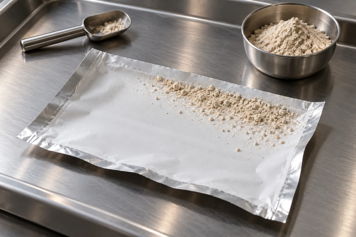
Choose the compatible mating surfaces first, then compare dust tolerance using the actual film and product. An A/A fin arrangement gives a one-side-sealable laminate the appropriate surface pairing. Relative performance against a compatible A/B lap arrangement depends on the sealant construction, contamination and sealing conditions. Record those variables before choosing a seam for a dusty powder.
Bamps and colleagues studied three seal-layer formulations with ground coffee and blood-powder contamination. Contamination reduced seal strength and narrowed the useful temperature-and-time window in their experiments, while seal-layer composition affected performance. The study also found that hot-tack results did not predict contaminated seal strength reliably. These results support application testing of the intended bond; a fin-versus-lap selection needs trials of both feasible constructions with the proposed powder.
Identify how product reaches the contact area: examine the open film, filling path and collected packs by lane and operating state. Separate clean startup samples from samples collected during steady filling or after a restart. Use the same powder batch for a direct comparison and record the contamination condition consistently. If the laminate or sealant changes between candidates, retain that change in the comparison record so geometry and material effects stay distinguishable.
Related reading: Stick Pack Machine Problems and Solutions: Multi-Lane Troubleshooting, Seal Leaks & Dose Drift
Further reading: Bamps et al.: solid contamination and seal-layer composition, Packaging Technology and Science
What should the seal comparison record contain?
Evaluate separation force, failure mode and leakage as distinct observations. ASTM F88/F88M-23 covers the force needed to separate a specimen containing a seal and identification of specimen failure mode. Its discussion of specimen support also explains why a consistent test technique matters. Use the agreed method across the comparison, record specimen width and conditioning, and keep the reported units consistent.
Add a suitable leak check to the finished-pack evaluation and inspect the points where the longitudinal seam meets the end seals. A force result from one sampled strip answers a different question from whether the complete pack contains a channel leak. Set acceptance criteria around the product and distribution requirements before comparing candidates. Retain observations such as interfacial opening, film tearing or layer separation alongside the numerical results.
Trial the actual printed film on the intended forming and sealing arrangement. Changing from fin to lap can involve the former, film-edge positioning and longitudinal-seal hardware. Establish those requirements before ordering a production roll. A comparison record should connect the film code and drawing revision to the setup that produced each sample, so subsequent changes can be assessed against the same evidence.
Related reading: Stick Pack Machine Sample Testing
Further reading: ASTM F88/F88M-23: Seal Strength of Flexible Barrier Materials
Scroll horizontally to see all columns. Keyboard: focus the table and use the arrow keys.
| Record | Keep with each sample set | Decision supported |
|---|---|---|
| Film and geometry | Film code, A/A or A/B, strip drawing and overlap | Compatible interface and correct material allocation |
| Product and process | Powder batch, contamination condition, temperature, dwell and pressure | Behavior across the intended operating window |
| Run location | Lane, startup / steady run / restart | Where variation appears |
| Bond result | Separation force, units, method and failure mode | Consistency of the selected bond |
| Whole pack | Leak result and seam/end-seal junction observations | Finished-pack integrity |
Which seam should you put in the film brief?
Use fin sealing when the selected laminate provides a compatible inner-to-inner bond and that construction meets the pack requirements. Consider lap sealing when the inner and outer mating faces are compatible and the resulting overlap, artwork and equipment arrangement are acceptable. Compare accepted output after those conditions are met. The narrower strip is only one input to the material purchase decision.
For film quoted per square metre, a useful cost-driver equation is film cost per accepted pack = (B × R / 1,000,000) × q / y. B is strip width in millimetres, R is repeat length in millimetres, q is the quoted currency per square metre of the actual construction, and y is accepted packs divided by the equivalent number of film repeats purchased. Allocate parent-web trim to B or include it in the purchased-area calculation, consistently. Keep gauge, barrier requirements and print construction attached to each quote.
Use the same accounting boundary for both candidates. Include startup scrap and rejected packs in the yield record, and compare tooling, changeover, labor and product losses separately from film cost. A lap-capable surface construction can change the quotation, while a change in film gauge changes the relationship between area and purchased mass. Compare actual quotes for the specified materials instead of assigning a fixed premium to two-sided sealability.
To discuss a configuration with StickPackMachine, bring the proposed film structure, the developed strip drawing, the powder or product description and the required finished-pack checks. Include the lane count, repeat, rear artwork and current seam problem if this is a conversion. These inputs let the film, equipment and sample-testing discussion address the same pack. Use the buying-guide collection to connect this seam decision with dimensions, film specification and the wider equipment brief.
Related reading: Stick Pack Machine Buying Guides; Powder Stick Pack Machine: Auger Dosing; Stick Pack Machine Sample Testing
Discuss this configuration
Discuss on WhatsAppCommon Questions
Is an overlap seal the same as a lap seal?
Yes. In this context, lap seal and overlap seal describe the longitudinal construction in which an inner film face bonds to the opposing outer face.
Can I use the same film roll for fin and lap sealing?
Check both the mating surfaces and the developed strip width. A roll specified for inner-to-inner bonding may need a different outer coating, slit width and artwork layout for lap sealing; the equipment arrangement also needs checking.
Does a lap seal always use less film?
For equal body circumference and repeat, a lap seal uses less strip area when its overlap o is smaller than the combined fin allowances s1 + s2. Compare complete parent-web layouts and actual film constructions when assessing purchase cost.
Does greater seal strength prove that a powder stick pack is leak-tight?
Assess leakage separately. Separation force and failure mode characterize the sampled bond, while finished-pack checks examine leakage and the junctions between longitudinal and end seals.