
What belongs on a stick pack dieline?
A misplaced eye mark can waste a printed reel. A print-ready stick pack dieline must identify the scan track before the artwork is repeated across the reel. The dieline is the technical drawing that locates the film boundaries, folds or seam, seals, cut repeat and opening feature. Your designer places graphics against those references; your converter checks how that drawing will print and be supplied as a reel. Agree which dimensions describe the finished flat pack and which describe the unfolded strip.
Keep artwork, technical dimensions, cut and slit references, eye marks, and any white-ink separation on identifiable layers. Ask the converter to identify which layers print and which remain technical references. A colored seal-zone overlay should not accidentally become part of the printed background. Equally, a reference mark that disappears when exporting the production PDF leaves the printer with a different file from the one engineering reviewed.
Use the existing dimensions guide to settle pack geometry before this handover. Artwork release answers where the printed elements sit on that geometry. It cannot determine the product volume, forming tooling or required sealing conditions. Put the drawing number, revision, units and viewing side on the approval record, and use the same revision when discussing film with the machine supplier.
Related reading: Stick Pack Sizes & Dimensions Guide
How do lanes, slit lines and print repeat fit together?
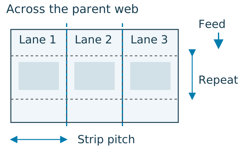
Lay out the parent web using the approved unfolded strip pitch and repeat. A multi-lane drawing must show where one strip ends and the next begins across the web, as well as the direction in which the reel feeds. Distinguish machine-direction repeat from cross-web lane pitch. Repeating a front-panel image at the finished pack width can omit the back panel and seam allowance.
For equal pitches, define parent-web width W, lane count N, unfolded strip pitch P, and separate left and right edge allowances E_left and E_right. The layout formula is W = N × P + E_left + E_right. Obtain P from the agreed strip and seam geometry, with its measurement boundaries shown. Check whether trim or seam material is already included so each allowance is counted once.
Mark the actual slit positions rather than assuming equal visible gaps between designs. Ask whether any trim or gutter is already included in the supplied pitch, and identify where edge material goes. A lane-numbered proof lets the team compare the artwork at the two web edges with the inner lanes. Different copy or flavors across lanes also need an explicit allocation so downstream collection cannot mix variants.
Add an unwind sketch that shows the outside face, print orientation and leading end as the reel enters the specified machine path. Words such as left, reverse or clockwise become ambiguous without a viewing direction. Obtain the converter and machine supplier's confirmation on the same sketch. The machine overview helps identify the equipment route being discussed; it does not replace the configuration drawing.
Related reading: Multi-Lane Stick Packaging Machines Compared; Stick Pack Film & Machine Compatibility
Where should the eye mark and clear scan track go?
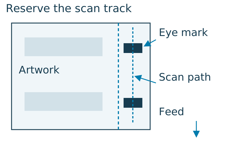
Reserve an optical scan track in the position specified for the installed registration system. An eye mark is a printed reference detected against its background so the control system can register the film. Confirm whether the proposed machine reads the parent web or individual strips, how many sensing positions it uses, and which edge the drawing references. One mark per lane is not a universal requirement.
Specify both mark dimensions, the distance to the chosen web datum and the relationship to the cut repeat on the machine-approved drawing. The required size depends on the sensor's sensing image, mark orientation and operating arrangement. A generic eye-mark size copied from another supplier's template can place the mark outside the scan path or leave too little detectable area. Ask the equipment team for the actual requirement before the converter locks the artwork.
Keep other graphics out of the agreed scan track. A dark border, barcode or repeated decorative stripe can create additional optical transitions in the same path. Confirm the selected mark and background on the actual printed laminate, including white ink or clear windows where used. Screen color contrast alone cannot establish what the installed sensor will distinguish.
Sensor manufacturers document different arrangements for reflective and transparent materials. The useful design decision is to identify the substrate, background and intended scan path early, then verify them with the installed system. Follow that sensor's own instructions for mounting and teaching. If a mark is detected inconsistently, also record film wander and transport behavior; enlarging a black rectangle is not a complete diagnosis.
Further reading: Banner Engineering: registration sensor instructions, Rev. F, June 2026
How much space should seals and tear notches keep clear?
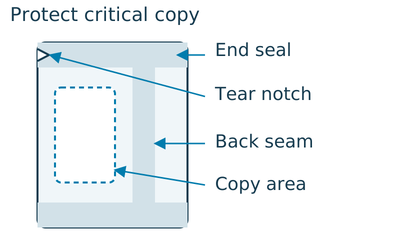
Place critical text and codes outside the approved seal, cut and tear-notch tolerance zones. Separate background bleed, which may extend beyond a nominal cut to avoid an unprinted sliver, from a safe area for information that must survive conversion and opening. Bleed does not authorize important copy to enter the seal or notch envelope. Ask the converter to set the bleed requirement for its process.
Identify the longitudinal back-seal construction before positioning rear-panel copy. A fin seal brings the inner sealant surfaces together; a lap seal overlaps the film edges and needs compatible contacting surfaces. These constructions use different artwork relationships. Show the agreed seam footprint and which printed area becomes concealed or folded after forming. Reserve the date-code location on the surface that remains usable in the finished pack.
Use an explicit tolerance budget for critical copy. Define c as nominal clearance from the relevant cut or feature boundary, t_print as the agreed print-position deviation and t_cut as the agreed cutting deviation in that direction. A conservative remaining margin is m = c − (t_print + t_cut). Use the converter’s agreed tolerances and the equipment drawing, then inspect formed samples to check that critical information stays within the usable area.
Rule of thumb: if m is zero or negative under the agreed worst-case deviations, move the critical copy or revise the tolerances before print approval. A positive result still needs the project's required residual margin. Apply a separate check around the notch and intended tear path so the opening feature does not remove the lot code or essential instructions. Verify opening on formed packs with the intended product and laminate.
Keep graphic clearance and seal performance as separate acceptance questions. ASTM F88/F88M-23 measures seal separation strength and identifies specimen failure mode; it does not prescribe an artwork margin or a universal stick-pack seal width. Agree the relevant seal checks with QA and the equipment team. A clean-looking printed seam alone does not establish its strength or package integrity.
Further reading: ASTM F88/F88M-23: public scope and significance
Which artwork failures should the approval proof prevent?
Compare the proof against physical film positions, rather than judging only whether a flat design looks balanced. Use the failure matrix below to decide what evidence is missing before printing. A symptom can have several causes, so keep the drawing, printed film and observed machine behavior together when investigating it.
Check all lanes and identify the condition in which a mismatch appears: first setup, stable running, reel change or restart. A common shift across lanes suggests a shared reference or transport question; an isolated lane also calls for comparison of that strip's print and mechanical position. Record observations before requesting an artwork correction so a transport problem does not become an unnecessary reprint.
Scroll horizontally to see all columns. Keyboard: focus the table and use the arrow keys.
| Design decision | Approval evidence | Dominant Failure Mode & Prevention |
|---|---|---|
| Repeat and lane pitch | Dimensioned parent-web proof, units and lane IDs | Cut or slit crosses essential print; approve unfolded strips and repeat against the machine drawing |
| Eye-mark track | Mark/background sample and sensing location | Missed or extra triggers; reserve a clear track and verify detection on the supplied laminate |
| Back-seal artwork | Formed sample and specified seam construction | Hidden or folded copy; place critical information outside the agreed seam footprint |
| Notch and coding area | Opening sample plus feature/coding envelope | Tear removes a code or interrupts legibility; check the tolerance zone and opened pack |
What should the artwork-release record contain?
Release a versioned drawing package that the brand owner, converter and equipment team can all identify. Keep the flat proof and formed-pack check together, with unresolved inputs marked for confirmation. The visible record below can be copied into the project brief; it is a handover checklist rather than an approved production dieline.
Before committing the production quantity, agree which printed sample or trial reel will establish registration, cut alignment and finished-pack appearance. Record the film specification and any changes to the ink or background in the scan track. Retain a sample from each lane with the corresponding drawing revision. A later artwork change that enters a scan, seal or notch area should reopen the affected check even when the finished dimensions are unchanged.
Related reading: Stick Pack Machine Sample Testing
Scroll horizontally to see all columns. Keyboard: focus the table and use the arrow keys.
| Record field | What to enter | Who confirms it |
|---|---|---|
| Drawing identity | Revision; units; viewing side; approved proof filename | Brand owner and converter |
| Web layout | Strip pitch; lane count; edge allowances; slit references; repeat | Converter with machine supplier |
| Registration | Scan-track datum; mark dimensions; background; cut relationship | Machine supplier with converter |
| Seals and opening | Back-seal type; end-seal footprints; notch and tear zones; residual margins | Equipment team and packaging QA |
| Reel orientation | Outside surface; leading end; unwind sketch; film specification | Converter with equipment team |
| Release evidence | Lane samples; observed cut alignment; opening and agreed seal checks; sign-off revision | Project owners for their respective checks |
Discuss this configuration
Discuss on WhatsAppHow do artwork revisions affect film waste and changeover cost?
Measure the cost of a revision over one defined production period. Separate obsolete printed stock from setup film actually consumed, then record operator time and repeat qualification work. Use measured film length where possible instead of estimating waste from reel diameter. If the same film is counted as rejected stock and setup consumption, the cost comparison will count it twice.
For constant web width, wasted film area A = W × L, with W in meters and L the recorded wasted length in meters. Incremental recorded cost = A × film rate per m² + additional operator hours × loaded hourly rate + separately documented reproof or trial charges. Record roll identity, incident and time window with those quantities so a corrective action can be compared against the same cost boundary.
Include effects after discharge in the same review. If lane-specific graphics identify different variants, confirm how the agreed collection and secondary-packing arrangement preserves that identity. An attractive reel proof is incomplete if the released sticks cannot be assigned correctly after cutting. Keep the artwork revision in the production record so the pack, film and downstream handling instructions stay aligned.
Registration, seal checks and drawing release
Banner Engineering’s R58E Expert Series instructions describe teaching a sensor against the registration mark and background. Check the installed sensor, scan direction and film surface against its instructions when releasing the artwork. Reflective or transparent films need the sensing arrangement reviewed with the actual substrate.
ASTM F88/F88M-23 provides a method for measuring seal separation force and failure mode. Keep the selected test technique consistent when comparing samples made from an artwork or film revision. Release the drawing, film grade and machine setup together so print clearance and seal performance remain traceable to the same package.
Related reading: Stick Pack Machine Sample Testing; Stick Pack Machine Buying Guides
Further reading: SICK support: mark detection on reflective and transparent materials