
What a stick pack machine footprint includes, and what it leaves out
Supplier literature usually quotes one set of overall dimensions: the length, width and height of the machine body. That figure describes a single configuration. The same machine family can be built in a standard and a wider version with different lengths, and the dosing unit, hopper, number of lanes and accessories all change the outline. Before you use a drawing, ask which configuration and which revision it shows.
The outline is also only the space the machine stands on. A working line needs room around it for product to arrive, for film reels to be brought in and loaded, for operators to stand at the controls and the hopper, for doors and guards to open, and for packs to leave the discharge toward inspection, counting or cartoning. In the room below, the machine stands in one taped zone among several. The others look empty while the line runs, and they are still used every shift.
Keep two kinds of weight apart as well. Fill weight is the dose in each pack and says nothing about how heavy the machine is. Machine mass is a supplier figure that needs its basis stated: the empty machine, the machine with product and film loaded, or the machine packed for shipping. The machine pages on this site give reference weight and footprint values for a four-lane reference configuration. They help compare options early. The quotation for your configuration states the figures, and the layout drawing for that configuration is what the floor plan should be fixed against.
Related reading: Multi-Lane Stick Packaging Machines Compared; Single vs Multi-Lane Stick Pack Machines
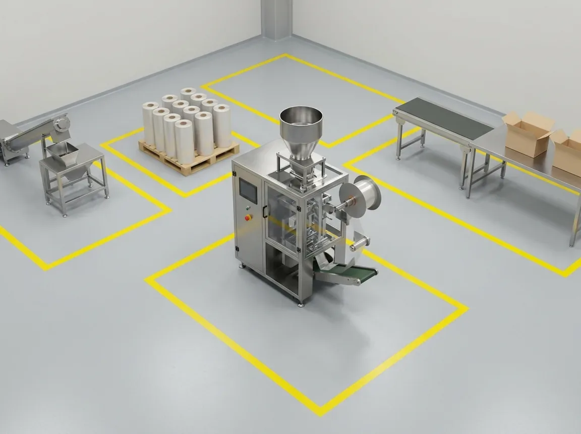
Draw the whole production line before reserving the room
Start the layout from the line, not the machine. Draw a top view of the room with the packing machine in it, then add every piece of equipment that touches product or packs before and after it: the feeder or conveyor that fills the hopper, any check-weighing or inspection unit and its reject path, the discharge conveyor, counting or collation, and secondary packing such as cartoning. Equipment catalogues list many of these as optional modules, and not every project needs them, so mark each one as integrated with the machine, supplied separately, or not included.
The joints between these items take space of their own. A packer can control a takeaway conveyor and exchange signals with equipment upstream and downstream, but the transfer height, the direction packs leave in, their orientation and any buffer between machines have to be agreed for your line. Use the table to record who supplies each interface and which drawing confirms it. A blank row is an open item, and it should stay visible until someone has answered it.
If the room is already fixed, place the outline of each module on your own floor plan at the same scale, with columns, drains, doors and existing equipment drawn in. That overlay shows conflicts a list of dimensions hides, such as a reject bin that blocks a walkway or a cartoner standing where the film pallets were meant to go.
Related reading: How a Stick Pack Machine Works
Scroll horizontally to see all columns. Keyboard: focus the table and use the arrow keys.
| Interface or zone | Information or drawing to obtain | Scope owner and confirmation |
|---|---|---|
| Product supply and hopper filling | Fill method, fill point position and height, feeder or conveyor outline | Supplier / site / other: ___; integrated / separate / not included |
| Film reel handling | Reel loading side, largest roll accepted, spare-roll storage position | Supplier confirms limits; site confirms storage: ___ |
| Controls and utilities | Panel position, connection points for power, compressed air and any extraction | Who supplies each connection: ___; drawing ref: ___ |
| Discharge and transfer | Discharge side, transfer height, pack orientation, signals to the next machine | Agreed between: ___; drawing ref: ___ |
| Inspection and rejects | Check-weigher or other inspection outline, reject path and bin position | Integrated / separate / not included; owner: ___ |
| Counting, collation and secondary packing | Outline of each module, buffer between machines, carton supply position | Integrated / separate / not included; owner: ___ |
| Cleaning, service and change parts | Door swings, part-removal positions, change-part storage on the layout | Supplier marks positions; site confirms: ___ |
Leave room for product loading and film reel changes
Product and film both arrive in bulk and leave as packs, and both need a route to the machine. Ask how the hopper is filled on the configuration you are buying: by hand from a platform or step, from a vacuum or screw conveyor, or from bags emptied at floor level. Each method puts an operator or a conveyor in a different place, and the fill point can need clear height above the hopper as well as floor space beside it.
Reel changes are easy to overlook because the reel stand is drawn as part of the machine. Suppliers place the unwind on a stated side of the frame, sometimes with the cutting and sensor adjustments close to it, so the side that faces a wall matters. Ask which side the reel loads from, how a full roll is carried to the stand on your site, where spare rolls wait, and whether a roll trolley or lifting aid needs room to turn. Plan for the largest roll you intend to buy. Your film supplier can confirm its diameter and weight against the machine's limits, which the film guide explains.
Write the answers into the layout as positions, not general statements. A note such as reel loads from the operator side, roll arrives on a trolley from the aisle, is something the drawing can be checked against. A phrase such as easy reel access is not.
Related reading: Stick Pack Film & Machine Compatibility
Check operating, cleaning and maintenance positions
The same machine needs different amounts of space depending on what is happening to it. While it runs, operators stand at the control panel, watch the seals and pull samples. During cleaning and format changes, guard doors are open, forming and dosing parts come out, and change parts need a table or rack close by. During maintenance, a technician may need to reach the back or the side of the frame. Ask the supplier to mark each of these positions on the layout, with the doors drawn open.
This page gives no clearances. The space a door sweeps, the room needed to withdraw an auger or a forming set, and the side a technician works from all depend on the frame and the parts of your configuration. A layout that only shows the running state can pass every check on paper and still leave a technician working in a narrow gap behind the machine.
Plan maintenance access from the manufacturer's instructions for the installed machine. Guidance on maintaining work equipment from the UK Health and Safety Executive recommends planning maintenance with the manufacturer's maintenance instructions, providing safe access and a safe place of work, and carrying out most maintenance with the machine stopped and its power isolated. The service positions on your layout describe that stopped, isolated state. They are not an instruction to work near a running machine; the manual and your site's own safety rules decide how the work is done.
Related reading: Stick Pack Machine Installation & Training; Stick Pack Machine Spare & Change Parts
Further reading: HSE: Maintaining work equipment
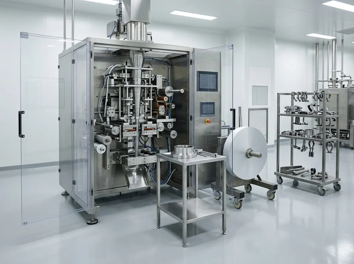
Confirm height, floor loading and the move-in route
Floor area is not the only dimension that can stop an installation. Check the clear height above the machine against its tallest point, including the hopper lid when it opens, any feed pipe entering from above, cable trays and lighting. Then check the route into the room separately. The machine may arrive in several pieces, each in its own packing, and the largest packed piece has to pass every door, corridor, turn and lift on the way.
Ask the supplier for the dimensions and mass of each shipped piece as well as of the assembled machine, the positions of the machine feet or supports, and the basis behind each mass figure. Your site's qualified people use that data to judge whether the floor and any platform can carry the load and how the machine will be moved into place. In the United States, the OSHA rule on walking-working surfaces requires each surface to support its maximum intended load and employees to have safe access and egress. Deciding whether a floor qualifies is therefore work for the people responsible for the building, not for a general guide.
Dividing machine mass by outline area does not show whether a floor is adequate, because the load sits on feet or a frame rather than evenly across the footprint. Keep the support data, the floor assessment and the agreed move-in plan with the order.
Related reading: Stick Pack Machine Installation & Training
Further reading: OSHA 29 CFR 1910.22: Walking-working surfaces, general requirements
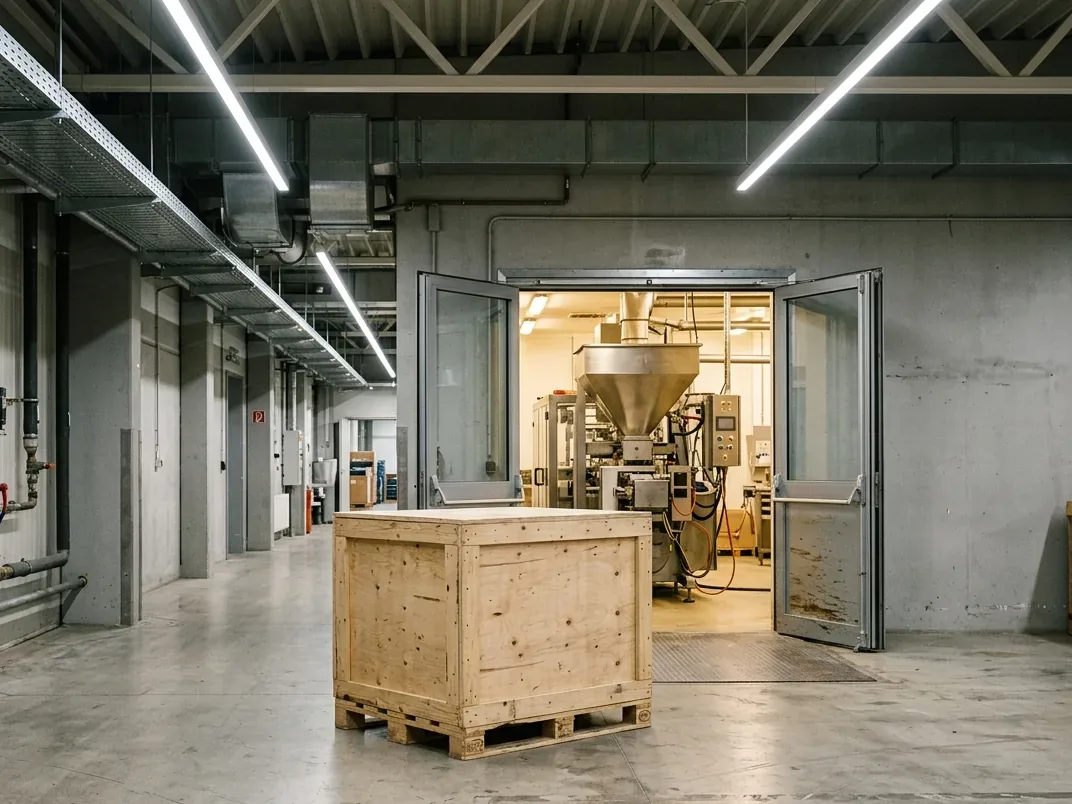
What to request from the equipment supplier
Request the items below once the configuration is clear enough to quote, and record each answer against the drawing revision it came from. When the configuration changes, for example a different dosing unit, an extra lane or an added check-weigher, the layout data changes with it, and older answers should be marked as superseded.
The checklist is a record, not an approval. A completed copy shows which facts the supplier has confirmed, which the site has confirmed and which are still open. It does not replace the installation drawing, the floor assessment or the agreement on who does what during installation. The machine-selection guide covers comparing quotations against one scope list, and the factory acceptance checklist covers what to verify before dispatch.
Related reading: How to Choose a Stick Pack Machine; Stick Pack Machine FAT Checklist
Scroll horizontally to see all columns. Keyboard: focus the table and use the arrow keys.
| Request | What it should state | Record |
|---|---|---|
| Configuration and revision | Model, lane count, dosing unit, accessories, drawing number and date | Ref: ___; confirmed / pending |
| Top and side views | Overall length, width and height; guards, cabinet, hopper, feeder and discharge marked as included or not | Ref: ___; confirmed / pending |
| Mass and supports | Net, operating and packed mass, each with its basis; foot or support positions | Ref: ___; confirmed / pending |
| Operating and service positions | Operator positions, door swings, part removal and change-part storage on the layout | Ref: ___; confirmed / pending |
| Reel and product loading | Reel loading side, largest roll accepted, hopper fill method and fill height | Ref: ___; confirmed / pending |
| Utilities | Connection points and requirements for power, compressed air and any extraction | Ref: ___; supplied by: ___ |
| Transfer and downstream scope | Discharge height and direction, signals to other equipment, inspection, reject, counting and cartoning | Integrated / separate / not included |
| Shipment and move-in | Number of packed pieces, packed dimensions and mass of each, unloading and positioning | Ref: ___; responsible: ___ |
| Site responsibilities | Floor assessment, platforms, route clearance and utility installation | Owner: ___; open items: ___ |
Sending your room plan and project requirements
To discuss a layout, share your project requirements and the room plan together. A floor plan with the room's length, width and clear height, its fixed obstacles and the route into it lets the proposed layout be checked against your site from the start. The product, dose range, pack drawing and accepted output decide the configuration, and the configuration decides the outline, so both belong in the same brief.
Say which equipment around the packer you already have and which you want quoted: product feeding, inspection, counting, cartoning or coding. Mark anything undecided as open rather than choosing a placeholder. StickPackMachine uses that brief to discuss a configuration and the layout data that comes with it. Installation support, responsibilities and any response-time commitment are set in the project agreement; the website does not state a standard response time.
Related reading: Stick Pack Machine Sample Testing; Request a Stick Pack Machine Quote
Method and sources
Written 15 October 2026. The method combines this site's published pages on lane count, machine operation, installation and the machine reference configurations with public manufacturer product pages and catalogues. Those pages describe configuration-specific overall dimensions, reel placement and access, optional check-weighing and downstream modules, and connections to conveyors and other equipment; they are used here for what a buyer should ask, not for numbers. Maintenance access and floor loading points come from the UK Health and Safety Executive guidance on maintaining work equipment and the US OSHA rule 29 CFR 1910.22. The page gives no dimensions, clearances, masses or floor ratings, and the figures show general room and equipment scenes, not a particular machine or site.