
Define the oxygen target before choosing the flush
| Input or item | Value or source | Why it matters |
|---|---|---|
| Residual oxygen target | Buyer-approved product specification | Defines the result and measurement timing |
| Lance depth and gas flow | Supplier drawing and product trial | Must fit the forming tube, powder path and seal clearance |
| Film barrier | Laminate supplier test report | Controls oxygen ingress after packing |
| Sampling method | Analyzer supplier protocol | Must suit the available stick-pack headspace |
Nitrogen flushing replaces air in the forming stick with a nitrogen-rich atmosphere before sealing. For oxygen-sensitive powders, the buying decision is whether that process can meet the product team’s written oxygen requirement at the required output. Gas-cylinder purity and a machine gas connection describe inputs. Acceptance needs a measurement inside the finished pack, made with an appropriate method at an agreed time.
A residual-oxygen target is a possible buyer-defined criterion tied to stability evidence for the packed formulation. Specify oxygen by volume in the sealed-pack headspace, the delay after sealing, the product and film, and how results are evaluated. Keep the initial release requirement and the later retention requirement with the product specification. Nitrogen flushing alone does not establish shelf life.
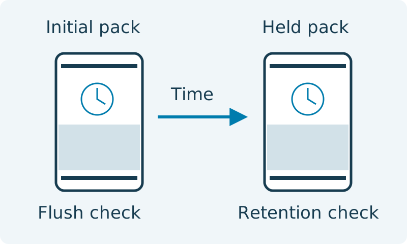
Write an upper-limit rule as measured O2 < approved O2 target when the product specification requires a strict inequality. Agree how measurement uncertainty and results at or near the boundary will be handled before the trial. Distinguish a fresh-pack release check from a later retention check: they answer different questions and require separately identified samples.
Related reading: Powder Stick Pack Machine: Auger Dosing
Place the lance using the forming-tube drawing
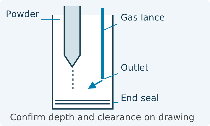
Confirm a gas outlet within the forming-tube and pack region, with its position defined relative to the powder discharge and the closing end seal. A forming-tube lance delivers nitrogen where air needs to be displaced. The supplier must show the actual arrangement for each lane; an upstream hopper blanket is a different location and cannot stand in for finished-pack evidence.
Insertion depth means the location of the gas outlet relative to a named datum on the assembly drawing. Ask the supplier to mark that datum, the outlet, powder exit, film path and full jaw movement envelope. An unexplained insertion length cannot tell you whether the outlet reaches the intended region or interferes with filling. Keep access for cleaning and change parts in the review. Any adjustment belongs in the supplier’s approved setup procedure.
Choose depth and flow together in the product trial. Record the starting configuration, change one variable at a time and compare pack oxygen, fill behavior and seal condition. A deeper outlet or greater flow is not automatically better: powder movement, restricted clearance and disturbed filling can make the setting unsuitable. Retain a drawing revision and setting record for the accepted configuration, so a later tube or dose change triggers a review.
Pair the flush with film and seal evidence
Choose the laminate from product-protection evidence and its behavior on the packer. Aluminum-foil and metallized-film structures are candidate barrier routes, but the layer name alone does not establish the finished stick’s oxygen retention. Request the complete structure, oxygen transmission rate, test conditions and sealant information. Then assess the actual supplied film after forming, handling and sealing.
ASTM D3985-24 covers an oxygen-transmission test method for plastic film and related materials. Its public scope concerns transmission through material, not the residual oxygen percentage inside a finished stick. Use a comparable film report to evaluate barrier performance; use a separate headspace measurement to evaluate the gas flush. Neither report alone establishes the product’s shelf life.
Keep seal cleanliness in the same review. Powder at the back seam or end seal, wrinkles and unsuitable sealing conditions can compromise retention even when the laminate has a strong barrier report. Ask the supplier to document the sealing setup and an appropriate integrity-check method with the chosen product and rollstock. A visually neat seam is useful inspection evidence, but it cannot replace the agreed integrity check.
Related reading: Stick Pack Film & Machine Compatibility
Further reading: ASTM D3985-24: public scope and significance
Scroll horizontally to see all columns. Keyboard: focus the table and use the arrow keys.
| Control route | Evidence to request | Dominant Failure Mode & Prevention |
|---|---|---|
| Forming-tube nitrogen flush | Lance drawing; gas setting; sealed-pack O2 by lane | Insufficient displacement or disturbed filling; verify outlet position and flow in the product trial |
| Aluminum-foil laminate | Complete structure; barrier report; formed-pack checks | Damage or a leaking seam defeats retention; qualify film handling and sealing |
| Metallized laminate | Complete structure; comparable barrier report; retention evidence | Assuming metallic appearance proves barrier; verify the supplied grade and finished pack |
| Sealing process | Settings, cleanliness and agreed integrity method | Powder or folds in the seal; control the filling/sealing interaction and inspect trial packs |
Measure headspace oxygen with a method that fits the stick
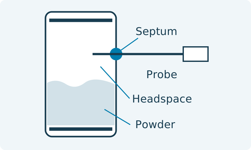
Use a headspace method suited to the gas volume available in the filled stick. An extracting analyzer needs a suitable sample volume and sampling arrangement; a small headspace may require a different instrument or accessory. Ask the analyzer supplier to confirm compatibility with your actual pack. State the calibration or verification procedure, sampling location and treatment of suspect measurements in the trial plan.
Needle-based methods can enter through a septum. PreSens describes insertion with the sensor protected inside the needle, followed by measurement after deployment. Follow the selected instrument’s own instructions rather than transferring one probe’s procedure to another analyzer. Keep the sampling point in the headspace and discuss powder-contamination control with the instrument supplier. A punctured pack belongs to that measurement record and should not become the later sealed retention sample.
Use separate identified packs for each measurement time. Record lane, sample ID, seal time, test time, oxygen result and any abnormality. Retain the operating conditions alongside the results: product batch, dose, film lot, machine cycle setting, gas supply and lane flow. Decide the sampling frequency and acceptance rule with QA before running; the plan must not quietly exclude a weak lane or discard a restart failure.
Further reading: PreSens: needle-type measurement in small headspace packages
Separate initial flushing from later oxygen retention
Compare initial packs with separately held sealed packs to decide which part of the process needs investigation. High oxygen immediately after sealing directs attention to gas supply, displacement, timing or the measurement method. A later increase adds film permeation and package integrity to the investigation. Treat this as a diagnostic sequence; it does not identify a root cause without further checks.
If only one lane differs, compare that lane’s flow path, outlet position, filling behavior and seals with the others before changing the common supply. If all lanes change together, check shared inputs and instrument verification. Include stops and restarts in the proposed trial because a result collected only during settled running does not describe those transition packs. Specify which packs are segregated until the accepted process has resumed.
Compare measured supply-gas oxygen with the approved pack target before increasing flow. If the supply concentration is already at or above that target, investigate the gas source first. In an ideal displacement or mixing model, flushing alone cannot make the pack oxygen concentration lower than the incoming gas. For acceptance, verify finished packs; a lower supply-gas value still leaves retained air and air entering during filling to evaluate.
Further reading: Package-gas, leak and barrier checks for coffee packaging
Calculate gas use per accepted stick on one shift basis
Compare gas consumption against accepted production over the same period. Define Q as total metered flow in L/min, t as gas-on minutes and N as accepted sticks during that shift. For constant flow, V = Q × t and gas per accepted stick = V / N. If flow changes through the shift, add each measured flow-times-duration interval. Keep volume reference conditions consistent across meters and supplier quotations.
Measure each lane’s flow or the combined supply at a stated volume reference condition. For changing flow, total gas volume V = Σ(Q_i × t_i), with each interval covering its actual gas-on duration. Gas per accepted stick = V/N, where N is the accepted count over that same window. Include startup, pauses and restart purge in the metered record, then compare settings against finished-pack oxygen results and accepted output.
Build the cost comparison around that same shift. Shift cost = gas used × gas unit rate + rejected product and film cost + testing consumables and labor + allocated supply-system cost. Include gas consumed during setup or stops in the metered total; do not add it again as another gas allowance. Compare delivered gas and generation using your own rates, demand profile, electricity, maintenance and supply charges. The machine’s flushing option and the gas supply are separate quotation items.
Related reading: Stick Pack Machine Price: Budget & Quote Guide
Make the sample trial deliver a traceable record
Agree the trial output before sending powder and film: a lane-resolved oxygen record tied to the actual configuration, with fill and seal observations. Include the production condition you want evaluated and the way stops, restarts and suspect packs will be handled. Ask who supplies the gas, analyzer and film checks so an omitted instrument does not emerge only when acceptance begins.
Use the visible fields below as the handover record. Leave an unknown input marked for confirmation instead of filling it with a guessed specification. Retain both passing and failing observations and the changes made between runs. Once a candidate setup meets the agreed trial criteria, transfer its scope into the factory acceptance plan; a sample exercise and contractual acceptance are different decisions.
Related reading: Stick Pack Machine Sample Testing; Stick Pack Machine FAT Checklist
Scroll horizontally to see all columns. Keyboard: focus the table and use the arrow keys.
| Record field | What to enter | Why retain it |
|---|---|---|
| Product and pack | Formulation/batch, dose, stick drawing and film lot | Connects results to the tested material and geometry |
| Configuration | Lane ID; drawing revision; outlet location; cycle setting | Makes the accepted setup identifiable |
| Gas | Source; measured supply O2; per-lane flow; reference conditions | Separates supply from pack displacement |
| Measurement | Sample ID; seal/test times; method; instrument verification; O2 result | Keeps sampling and uncertainty traceable |
| Retention | Separate sealed sample IDs; hold conditions/time; later results | Checks atmosphere retention independently |
| Disposition | Acceptance rule; defects; rejected packs; changes and reruns | Prevents averages from concealing a failing condition |
Discuss this configuration
Discuss on WhatsAppConnect oxygen measurements with the selected configuration
Use ASTM D3985-24 film oxygen-transmission data together with finished-pack integrity and headspace measurements when assessing oxygen protection. PreSens’s small-headspace guidance describes stabilized needle-sensor entry through a septum; follow the selected instrument procedure and record the delay after sealing. Compare initial and retained samples under the product team’s stability plan.
Carry the chosen gas path, measurement method and oxygen requirement into the powder-machine specification and acceptance plan. Identify who supplies the gas and measurement equipment, and retain the tested film grade, product lot and settings with the results. Review changes to the powder, film or flushing arrangement against those same acceptance conditions.
Related reading: Powder Stick Pack Machine: Auger Dosing; Stick Pack Machine Sample Testing; Request a Stick Pack Machine Quote
Further reading: Air Products: guide to modified atmosphere packaging, gas analysis and VFFS